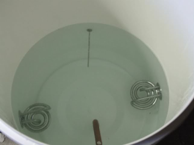
HLT Temp Control, with PICs
-
JackA
Re: HLT Temp Control, with PICs
Sorry to drag up this old thread, but I was wondering where you bought your temp probe from:


-
kevinjersey
Re: HLT Temp Control, with PICs
After having success with a TC10 and fermenting fridge, I am having a go at putting a PID together similar to yours for the HLT.
Can I ask what I think is a silly q.......Why do you have 2 SSR's, I know there are 2 elements, but would wiring them both through 1 SSR work (assuming it can take over 20amps, 10amps per element)?
Can I ask what I think is a silly q.......Why do you have 2 SSR's, I know there are 2 elements, but would wiring them both through 1 SSR work (assuming it can take over 20amps, 10amps per element)?
- Aleman
- It's definitely Lock In Time
- Posts: 6132
- Joined: Sun Jun 03, 2007 11:56 am
- Location: Mashing In Blackpool, Lancashire, UK
Re: HLT Temp Control, with PICs
While the SSR can control upwards of 25 or 40A the issue is how do you deliver them to the SSR . . . you can't simply plug into a 13A socket . . . Hence using two SSR's so that the feed can come from a 13A Supply
-
kevinjersey
Re: HLT Temp Control, with PICs
Yes of course the 13amp socket limit doh....Which is why I can run 2 kettles in my kitchen on the same ring main without blowing the circuit.
But why on the control box is there a switch to run 1 element or the other and not both at the same time? Is 1 being controlled manually till it reaches the boil then only 1 element required to keep on boiling, or have I misunderstood.
But why on the control box is there a switch to run 1 element or the other and not both at the same time? Is 1 being controlled manually till it reaches the boil then only 1 element required to keep on boiling, or have I misunderstood.

