WH7016E temp controller & Cedaronics Enclosure/heat trace

The forum for discussing all kinds of brewing paraphernalia.
beermonsta

WH7016E temp controller & Cedaronics Enclosure/heat trace

Post by beermonsta » Sun Dec 25, 2011 8:50 pm

Merry Christmas everyone!

http://www.willhi.com/Documents/WH7016Edatasheet.pdf The controller manual.

http://www.ebay.co.uk/itm/280736256740? ... 3D1&_rdc=1 The controller from ebay.

http://www.cedaronics.co.uk/ supplier of enclosure and heat trace cable.

Image
Warning – picture heavy post (well what else do you do after a Christmas meal?!)

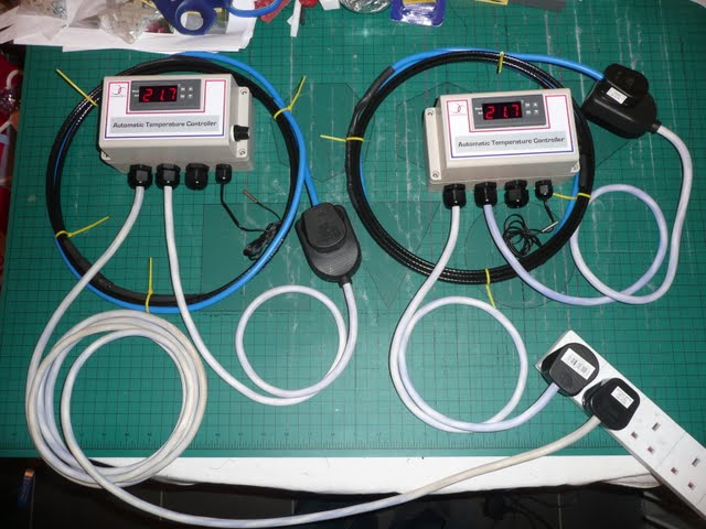
So this is the completed heating controller housed in a Cedaronics case controlling a trace heat wire for a condensation boiler. The control unit can be used to control either a cooling or heating circuit as well so has many uses for brewing too such as fermentation temperature control, HLT control etc.
Here is how it was made…

Image
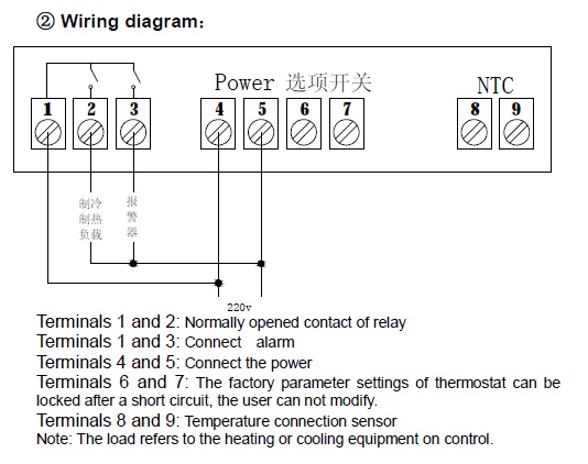
First of all the wiring diagram for the WH7016E. Please note this looks exactly like an STC1000 but although it has the same look and dimensions it doesn’t have the exact same functionality. The major differences are it will only do either heating or cooling – in other words this needs to be selected in the controllers software when powering up for the first time. It only has 5amp relays internally so be aware of the power limitation it can control (or make sure you use a suitable rated relay to switch higher currents). Most annoyingly it has an alarm output – which can be used to trigger other devices when the measured temp deviated by up to 15’C – but it has a internal beeper to let you know! Having said that – it was £10 and ideal for my purposes...read on. Oh they Cantonese bit below No2 reads heating/cooling control and the bit below No3 reads “alarm”

Image


Image
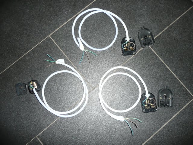
First up was making the plugs and sockets up. I’m making two control units, one for me and one for my mum as one of her Christmas presents. One plug and cable is missing as I already have it made up. The plugs/trailing sockets are from Maplin, and are supposedly rubber – although they feel more like a rubberised plastic to me, not like the old fashioned decent rubber sockets. The cable is 2.5mm heat proof cable – and this is definitely rubber based. I chose this in case I decided to put a large current through the cable for controlling a 3kw/13 Amp element.

Image
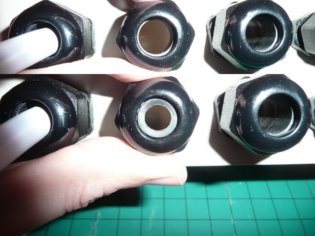
This is split shot (spot the difference!) showing the compression glands on the bottom of Tim’s (Cedaronics) enclosures – as you can see when the nut is turned it compressed a rubber olive that grips and seals against the cable.

Image
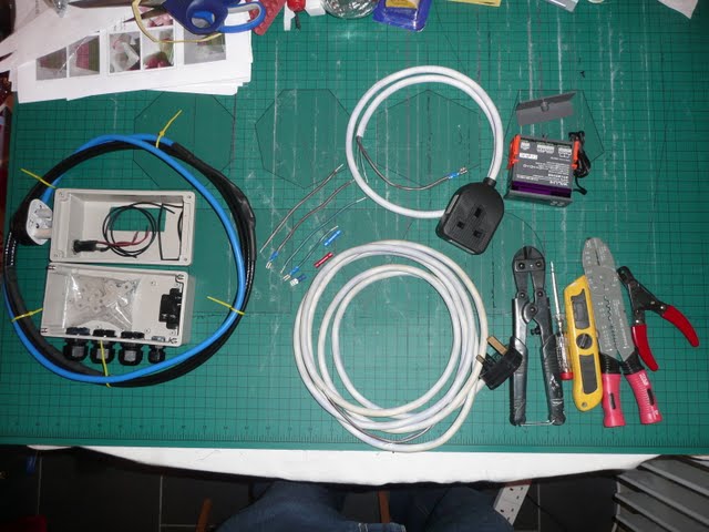
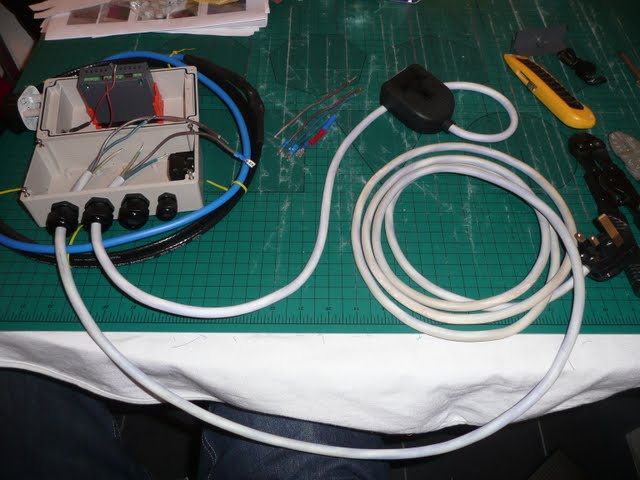
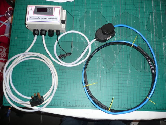
Here is an overview of all the equipment and tools I used. On the far left is what Tim supplied – the enclosures and trace heat cable. In the middle is the cabled up plug and socket, made earlier. You can also see some of the internal wiring with crimped terminals pre-made. Top right is the controller. Bottom right is the Tools: mini-bolt (wire) cutters, electricians screw driver, Stanley knife, crimping tool, wire strippers.

Image
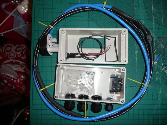
Here is a close-up of the Cedaronics kit. Tim supplies these ready made or as I have got here – ready to make up. The stuff is of very high quality and I’m impressed that he has thought of everything that is needed. The enclosure is pre-cut out to fit the STC-1000 and similar type controllers. He has supplied a gasket to make the seal better to maintain the IP rating. Also there is a loose gasket seal that gets poked around the edge of the box to make it seal. There is a Fuse which I will use to protect the controller. Also a bag of fixings to help, well, fix things in place. For me most of this bag was not required but nice to have in case. You can also see a relay which will allow the controller to power higher currents so the enclosure and the controller can power a 13kw element easily and safely. At the bottom you can see the grommets as show above. One for power input, one for heating output, one for cooling output (not required for my purposes) and one for the temperature sensor. You can also see the trace heating cable which has 1 meter of cold blue wire before leading onto the 2m of black trace heating cable.

Image
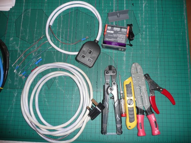
close-up of the middle bits!

Image
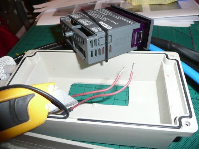
First job – fitting the gaskets – one for the controller, one for the enclosure that gets trimmed to size.

Image
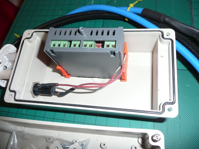
and fitted. You can see the controller has been fitted making use of the orange retaining clips.

Image
The power in and power out cables are fed through the grommets. I have also attached one of the fuse wires to the power in (No.4) on the controller.

Image
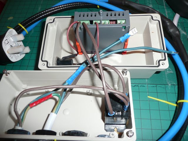
The earth wires have been looped through as there is no reason to earth a plastic enclosure! And the controller/relay doesn’t require an earth. The neutrals are looped with two wires, one for the relay (coil), and one for the controller (No.5). The incoming live is ready to connect to the Normally Open switch on the relay. The live is then also branched off to provide power for the switched live (heating/cooling) on the controller (No.1).

Image
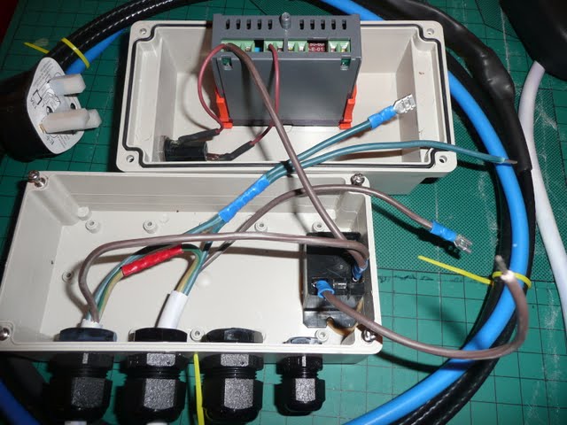
Notice the other fuse wire steals power from the No.1 connection, goes through the fuse before supplying the controller at No.4.
There are several ways that the power can be split but my way of thinking is that the incoming power needs the most direct route to the device that draws the most power, as there is less electrical resistance between connections so minimising localised heating etc for safety reasons, with the other items such as the controller needing far less current.

Image
A step closer.

Image
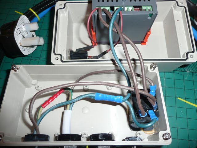
and all done except the temp probe.
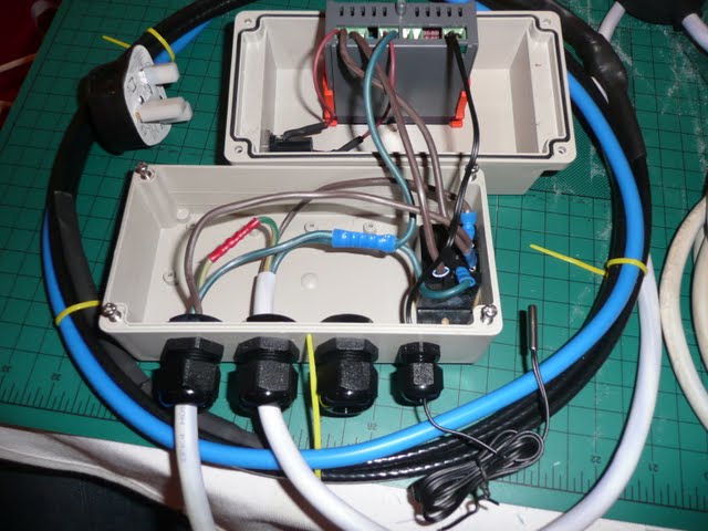
Image
et voila!

Image
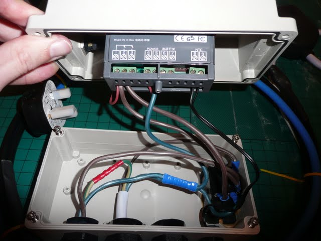
and for reference here you can see the wiring diagram on top of the controller. My pigeon-cantonese says that No6 & 7 says “select switch” – or in the manual it says “The factory parameter settings of thermostat can be locked after a short circuit, the user can not modify” or in normal English – the device can be factory locked out by short circuiting between 6&7 to prevent users for messing around with the software settings!

Image
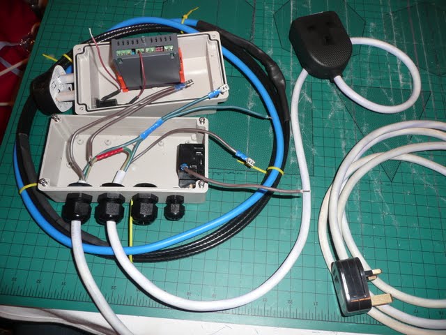
Here is one completed ready to install
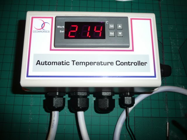
 :D

Image
initial turn on.

Image
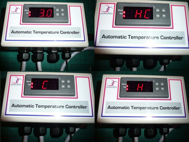
Setting up the controller. Top left = Press set once, then down arrow to lower the target temp to 3’C to switch the power on below this to the trace cable. Top right = hold set down for 3 seconds, and HC is displayed. Bottom left = currently set to cooling mode so…Bottom right = changing the controller to heating mode.

Image
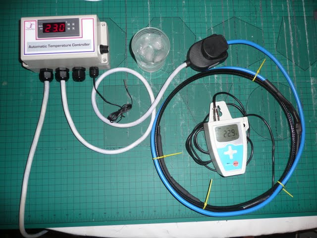
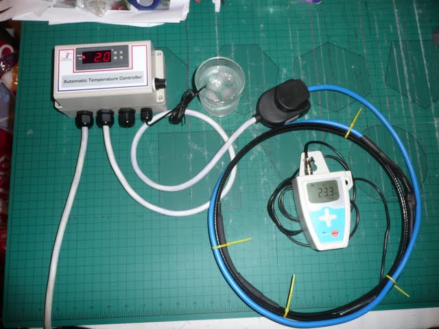
Ready to test. Note the temp readouts in air are around 23’C on both the controller and my handheld temp datalogger.

Image
Dropped the controllers probe in iced water. Here it is reading 2’C and has only just turned power onto the heat trace wire. The handheld probe is between three of the trace heat wires. (you shouldn’t really have the wires overlapping/wrapped up as in theory it could overheat but this was a quick on – off test for a short period. Same for power cables too!)

Image
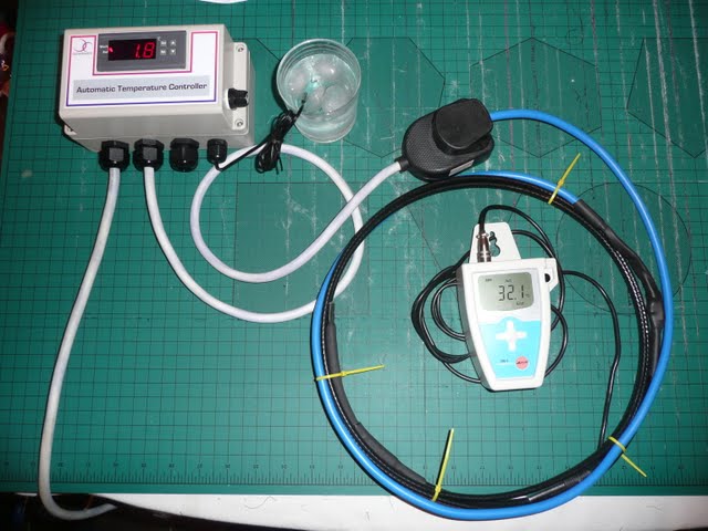
and the trace cable is heating up nicely – woop woop!

Image
and the finished pair. One got wrapped and then was unwrapped by my mum this morning – she’s chuffed her boiler isn’t going to stop working through freezing temperatures again.

Many thanks to Tim for supplying the controller box and trace heating wire – great quality products.

Merry Christmas
BeerMonsta.

any questions - just ask :)

User avatar
Andy
Virtually comatose but still standing
Posts: 8716
Joined: Fri Nov 18, 2005 1:00 pm
Location: Ash, Surrey
Contact:

Re: WH7016E temp controller & Cedaronics Enclosure/heat trac

Post by Andy » Tue Apr 10, 2012 8:30 am

You see the Chinese writing on the wires from 2 & 3 ? I'm no expert in Cantonese but I'm willing to bet 2 = "heater/cooler"* and 3 = "alarm"*

* or similar

:)
Dan!

troublebrewing

Re: WH7016E temp controller & Cedaronics Enclosure/heat trac

Post by troublebrewing » Tue Apr 10, 2012 7:56 pm

Impy wrote:Hi Beermonsta,

Can you confirm that the wiring diagram is correct? Because it looks like it's creating a short where the live wire going into 1 is being connected to neutral wires (2 & 3). From the looks of it as soon as the device decides any heating or cooling needs to happen it'll complete the circuit between 1 and 2 or 1 and 3 then that means a live wire is being connected directly to a neutral wire (or so the diagram seems to show). Shouldn't 2 & 3 go directly to the heater and cooling devices? From looking at other wiring diagrams for heating controllers the Neutral wire going to 5 would normally just branch to the heating and cooling devices without being plugged into any other ports on the controller.

Thanks in advance for clearing it up.
Beermonsta is using the WH7016 etc., so I can't vouch for that, but that diagram is misleading - particularly to someone not familiar with wiring diagrams. You'll find that the connection with cables is shown by a black blob symbol on the picture. If it were a properly drawn schematic, the crossing over of one cable with another would be indicated by a sort of hump backed bridge affair. In this case, the wire appears to be shown touching the others (1+2), when in fact it is not.

Don't be tempted to join the cables in this way or you will probably go BANG!

Good luck with that.

Tim

beermonsta

Re: WH7016E temp controller & Cedaronics Enclosure/heat trac

Post by beermonsta » Fri Apr 13, 2012 7:41 pm

Impy just below the wiring diagram I wrote this
beermonsta wrote:... Oh they Cantonese bit below No2 reads heating/cooling control and the bit below No3 reads “alarm”
So what Andy is saying is right. You would place your heater/cooler where the chinese writing is in the diagram so the incoming live is switched by the WH7016, before providing power for your heater/cooler before then joining the neutral.

Be aware that No2 does BOTH heating OR cooling and that it is selected using options in the controller when you power on.
No3 is used to trigger an alarm. (although having said that it may be used, if you know what you are doing, to control something else)

killeriq

Re: WH7016E temp controller & Cedaronics Enclosure/heat trac

Post by killeriq » Fri Jun 15, 2012 12:30 pm

Hello,

Ive found your guide for this device, but as you put it into box is not
very clear to me how should i connect the cables.

because i have also the older model
[IMG]http://i230.photobucket.com/albums/ee16 ... h7016c.jpg[/IMG]

And i got it working when i find out this connection. So i wonder if you
could help me and send/post the connection of this one.

Thanks

beermonsta

Re: WH7016E temp controller & Cedaronics Enclosure/heat trac

Post by beermonsta » Fri Jun 15, 2012 2:58 pm

I'm afraid I can't take any more pictures as it is now fully (permanently) installed. The photos above are as clear as I could make them showing the wiring but in all seriousness I wouldn't recommend copying Anyones wiring based on just a picture. You need to be able to understand the wiring diagram first and be competent enough to wire Mains powered devices yourself. Please try to find someone who can help you in person understand the wiring diagram and help you wire it up. Stay safe. BM.

killeriq

Re: WH7016E temp controller & Cedaronics Enclosure/heat trac

Post by killeriq » Fri Jun 15, 2012 3:01 pm

[quote="beermonsta"]I'm afraid I can't take any more pictures as it is now fully (permanently) installed. The photos above are as clear as I could make them showing the wiring but in all seriousness I wouldn't recommend copying Anyones wiring based on just a picture. You need to be able to understand the wiring diagram first and be competent enough to wire Mains powered devices yourself. Please try to find someone who can help you in person understand the wiring diagram and help you wire it up. Stay safe. BM.[/quote]

cant you just paint me some?

cos i dont understand how can be number 2 and 3 after together with 5.

I wrote to different sellers and all of them are sending me just that manual, they have no idea when im asking about details

User avatar
Andy
Virtually comatose but still standing
Posts: 8716
Joined: Fri Nov 18, 2005 1:00 pm
Location: Ash, Surrey
Contact:

Re: WH7016E temp controller & Cedaronics Enclosure/heat trac

Post by Andy » Fri Jun 15, 2012 3:13 pm

Ignore connector 3, that's only used if you want an alarm to trigger when the unit switches to heating/cooling. Connector 2 goes to your heating/cooling device "live" input with the "neutral" side of the heating/cooling device then wired to the mains neutral wire (which also goes to terminal 5 of the control unit).
Dan!

killeriq

Re: WH7016E temp controller & Cedaronics Enclosure/heat trac

Post by killeriq » Fri Jun 15, 2012 3:27 pm

[quote="Andy"]Ignore connector 3, that's only used if you want an alarm to trigger when the unit switches to heating/cooling. Connector 2 goes to your heating/cooling device "live" input with the "neutral" side of the heating/cooling device then wired to the mains neutral wire (which also goes to terminal 5 of the control unit).[/quote]


Thanks Andy! so could u have a look on my connection if is OK? Thanks

[IMG]http://i230.photobucket.com/albums/ee16 ... resize.jpg[/IMG]

hmm somehow the BBCode is disabled for me :(

http://i230.photobucket.com/albums/ee16 ... resize.jpg
Last edited by killeriq on Fri Jun 15, 2012 3:57 pm, edited 1 time in total.

User avatar
Andy
Virtually comatose but still standing
Posts: 8716
Joined: Fri Nov 18, 2005 1:00 pm
Location: Ash, Surrey
Contact:

Re: WH7016E temp controller & Cedaronics Enclosure/heat trac

Post by Andy » Fri Jun 15, 2012 3:42 pm

That looks like it will work, but a few comments :)

1. Your diagram annotation (red text) shows the positive ( + ) connections using blue wires and negative ( - ) using brown wires. This is the wrong way round ( blue = neutral, brown = live).
2. You're also using a yellow coloured wire (earth) to join 2 and 5 - not a problem but convention would use the appropriately coloured wire.
3. Normally I'd connect the live supply to connector 1 and then use connector 2 to go to the heating/cooling device but you're doing it the other way round.

None of the above will stop your circuit working however.

Also, I see the spec of the controller is 220v, 5A - is your heater/cooler device compatible with that rating ? This may be a problem if you're using a high power device.
Dan!

killeriq

Re: WH7016E temp controller & Cedaronics Enclosure/heat trac

Post by killeriq » Fri Jun 15, 2012 3:51 pm

1. ah i didnt knew which cable is + or -, so i just connect it that way ;) ok so i will connect it opposite
2. didnt had other cable so ive used "earth" left over - thing is i bought extension power cable and put it on half, so this way i dont have to cut the cord ends of heating/cooling device
3. so the yellow cable from 5 should go to 1 (instead of 2) and then the brown device cable to 3

about the spec - ive already used WH7016E with the heating cable 30w and it was working fine.

User avatar
Andy
Virtually comatose but still standing
Posts: 8716
Joined: Fri Nov 18, 2005 1:00 pm
Location: Ash, Surrey
Contact:

Re: WH7016E temp controller & Cedaronics Enclosure/heat trac

Post by Andy » Fri Jun 15, 2012 3:54 pm

killeriq wrote:1. ah i didnt knew which cable is + or -, so i just connect it that way ;) ok so i will connect it opposite
2. didnt had other cable so ive used "earth" left over - thing is i bought extension power cable and put it on half, so this way i dont have to cut the cord ends of heating/cooling device
3. so the yellow cable from 5 should go to 1 (instead of 2) and then the brown device cable to 3

about the spec - ive already used WH7016E with the heating cable 30w and it was working fine.

>3. so the yellow cable from 5 should go to 1 (instead of 2) and then the brown device cable to 3

Yellow from 5 to 1
Brown from device to 2

And a 30W cable will be fine with a 5A unit :)
Dan!

killeriq

Re: WH7016E temp controller & Cedaronics Enclosure/heat trac

Post by killeriq » Fri Jun 15, 2012 3:57 pm

[quote="Andy"][quote="killeriq"]1. ah i didnt knew which cable is + or -, so i just connect it that way ;) ok so i will connect it opposite
2. didnt had other cable so ive used "earth" left over - thing is i bought extension power cable and put it on half, so this way i dont have to cut the cord ends of heating/cooling device
3. so the yellow cable from 5 should go to 1 (instead of 2) and then the brown device cable to 3

about the spec - ive already used WH7016E with the heating cable 30w and it was working fine.[/quote]


>3. so the yellow cable from 5 should go to 1 (instead of 2) and then the brown device cable to 3

Yellow from 5 to 1
Brown from device to 2

And a 30W cable will be fine with a 5A unit :)[/quote]


Ah ok cos u wrote 3 in post before, but as u mention before 3 is alarm, so will do as u say, make a picture and try it.

Thanks once again :)

User avatar
Andy
Virtually comatose but still standing
Posts: 8716
Joined: Fri Nov 18, 2005 1:00 pm
Location: Ash, Surrey
Contact:

Re: WH7016E temp controller & Cedaronics Enclosure/heat trac

Post by Andy » Fri Jun 15, 2012 3:59 pm

I edited my post after you read it :)
Dan!

killeriq

Re: WH7016E temp controller & Cedaronics Enclosure/heat trac

Post by killeriq » Sat Jun 16, 2012 12:07 pm

Hi andy, so ive changed the connection and connect it this way, seems is working.
Just plz check if is that way as u ment it. Thanks!

Image

Post Reply