
Reading all I could on the subject of PWM vs Time Proportional Heating Control I decided to do some comparison runs.
I created a simulation routine to save Me having to run the tests in a real world environment.
This helped speed the whole process of tuning the PID settings Kp Ki and Kd.
Auto Tune worked with several degrees of overshoot.
In the end I went for a step test tuning method.
Creating graphs from the output of the Arduino serial.print command over Bluetooth and recorded using Minicom on the RPI3.
I eventually got the overshoot down to 0.04C in simulation and 0.67C on a 33L test system.
I am working on removing the slight overshoot due to lag and will post the results when I achieve the 0.04C on the 33L system.
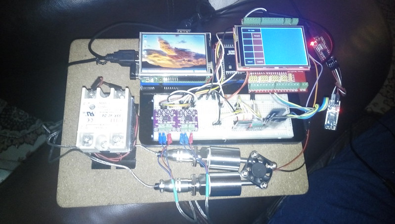
Here is the PID system.
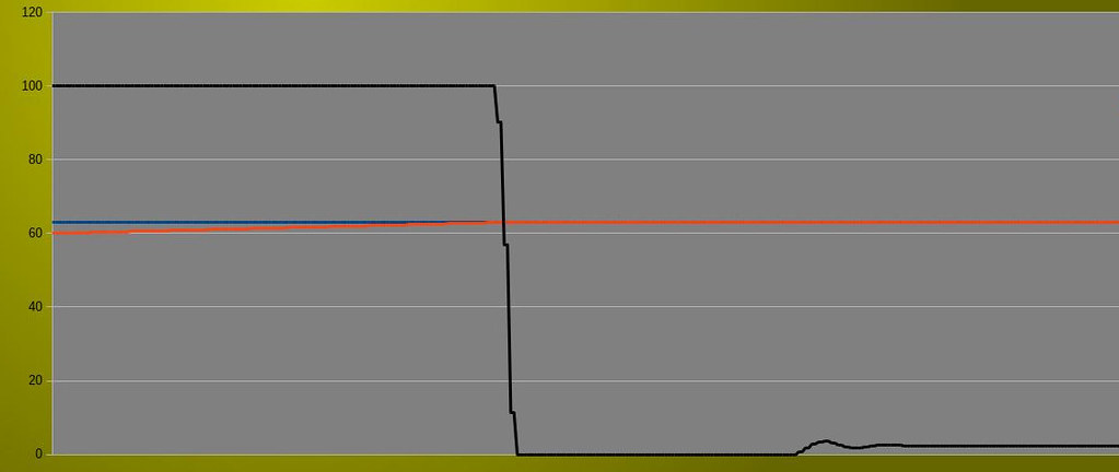
Here is a graph of the Time Proportional run.
Here is a graph of the PWM run.
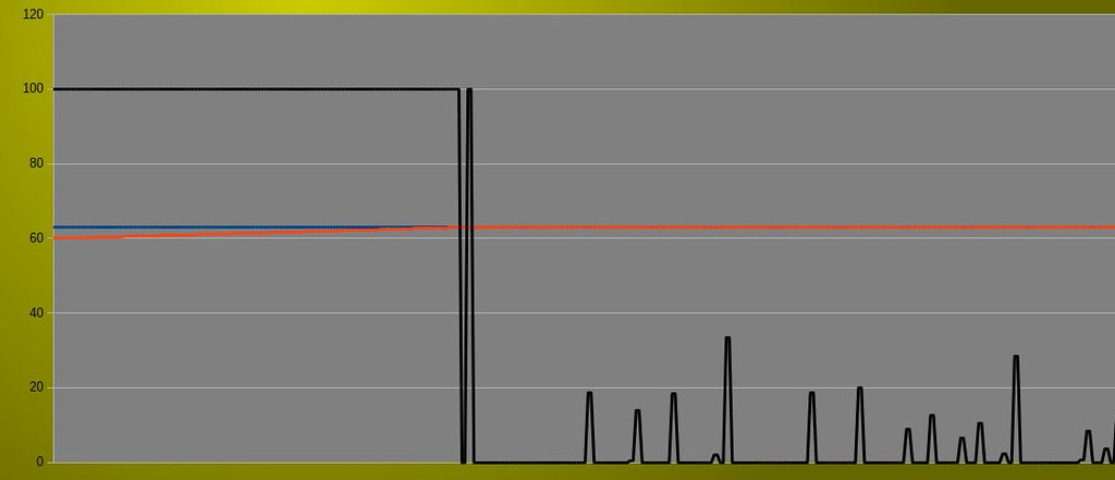
The Blue line is Set Point, Red is Process Variable and Black is the Output from the PID compute command.
I used the same Kp Ki and Kd values for each run.
Time Proportional reached a steady state very quickly with the Output settling at 2.35% and maintains the temperature at exactly 63C.
PWM has the Output ringing anything between 0.1% and 47% and maintains the temperature at exactly 63C.
Exactly the same code albeit for the analogWrite(RelayPin, Output); vs digitalWrite(RelayPin, HIGH/LOW);
I am hoping to get the PWM runs to settle to steady state of 2.35%
PID sample rate is 1000ms.

