HERMS at last!

The forum for discussing all kinds of brewing paraphernalia.
User avatar
edit1now
Under the Table
Posts: 1408
Joined: Wed Nov 28, 2007 5:09 pm
Location: North-west London

HERMS at last!

Post by edit1now » Sat Apr 26, 2008 4:37 pm

I have to thank Dan and Vossy and Mix and Andrew and Seveneer and anyone else whose ideas I been inspired by (whose ideas I've shamelessly ripped off).

Lots of pictures: sorry if you're on dial-up.

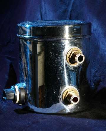
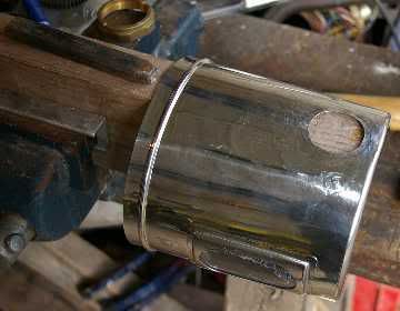
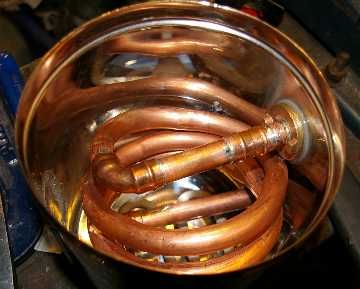
Here's the shiny porn shot, so we can get it over with:
Image

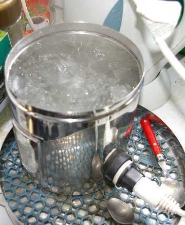
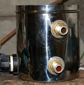
I started with a £6.50 stainless storage jar (about 3.4 litres to the top) from a kitchen shop in Southall (high quality Indian stainless products here):
Image

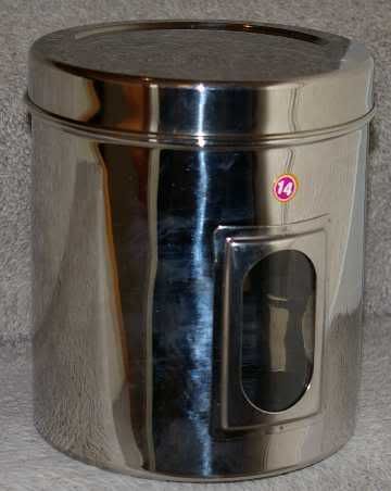
The window leaked, so I ran some food-grade silicone sealant round the inside.

I drilled a 40mm hole for the kettle element near the bottom, with a Bosch cobalt holesaw as recommended on JBK, and put the element in so I could see where to put the hole for the bottom tank connector. The lowest bit of copper tube had to definitely miss the element!

The jar is only 155mm diameter, so I had some trouble getting the kettle element to seal on the curved surface. I tried hammering it flat around the hole, but lacking an anvil with a long beak I had to resort to bodgery as usual. Using a club hammer held in the vice:
Image
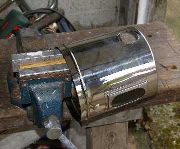
the chisel end of a big crowbar:
Image
a heavy right-angle bracket from an office partition thing:
Image
and finally a piece of 2x4 and a rivet set as a flat-ended punch:
Image
That's about as flat as it was ever going to get without some kind of concave punch-and-die system. Squashing it between two flat things, like a pair of lathe changewheels, had no effect, as the thin stainless (about 0.8mm) is very springy! Eventually I tried two rubber element washers between the element and the jar, and the afore-mentioned silicone sealant, and it worked. Look no leaks:
Image

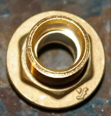
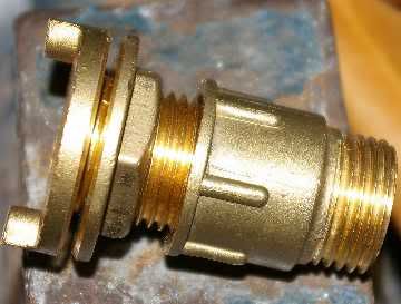
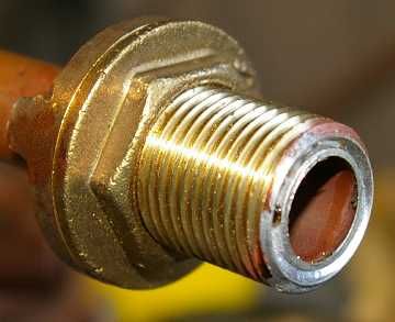
Unlike some of my heroes mentioned above, I decided to put the the tank connectors facing outwards (i.e. threaded part outside the heat exchanger) so I could screw on the Camlock couplings (if you take the compression nut and olive away you have a 1/2" BSP thread). The 15mm compression tank connectors have a step inside, where the pipe stops in normal use:
Image
so I drilled this out with a 15mm blacksmith's drill, doing a bit from each side:
Image
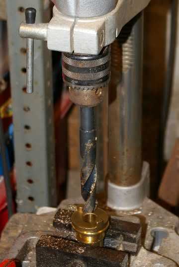
The tank connector was screwed into another 1/2" BSP thing I had, so the vice jaws couldn't damage the thread:
Image
I had some squirty cutting compound for drilling.

Next I soldered one of the connectors onto a stub of 15mm copper pipe (lead-free solder):
Image
and you can see my dodgy soldering at the back:
Image
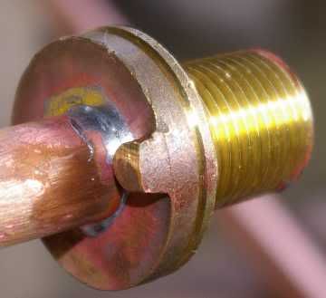
If like me you wind up with solder on the threads you'll have to hacksaw/file it off carefully otherwise nothing will want to screw on.

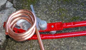
I own a cheapo pipe bender, from when I did the bathroom, so I found by trial and error that you can make a coil with it. Starting like this:
Image
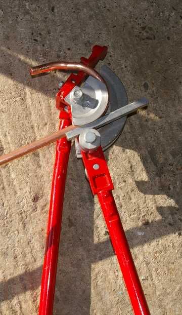
then you have to persuade the first and subsequent turns to miss the big curved thing (die?) on the pipe bender and not jam up anywhere:
Image
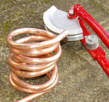
It's not pretty, on my first attempt. I got bored about here:
Image

First of all I tried the coil of pipe with a 15mm solder-ring elbow pointing away from the coil, but there was no way I could ever get the tank connector through the hole in the jar, so plan B had the end of the coil soldered to an elbow pointing inwards from the coil to the stub with the tank connector on, and then I tried it in the jar for fit:
Image
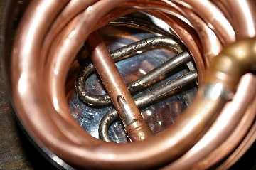
Obviously I had done too many turns!
Image
Cut it off, assemble an elbow and another stub of pipe, and find out where the top hole has to go. I did the holes for the tank connectors with a 20mm cobalt holesaw, which is what they had at Screwfix. Unfortunately you need about 21.5mm diameter to clear a 1/2" BSP thread, so I opened-out the holes and deburred them with the Minicraft drill and a little rasp bit. I now have a 22mm holesaw from Axminster Power Tools - they carry all the sizes.

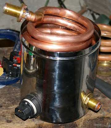
Here is the thing assembled with plastic tank washers and silicone sealant:
Image
Image
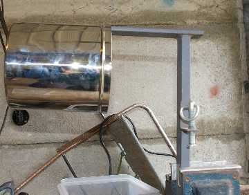
and here it is on a water test using horrible garden hose:
Image
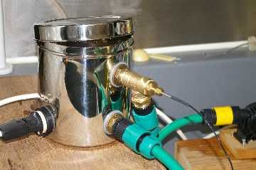
You can see the 1/2" BSP tee (from BES) on the top (the outlet) with the Pt100 probe in its compression fitting, pointing into the cross-ways stub pipe. Instead of doing-up the 1/8" compression fitting with the olive as supplied, I put a bit of self-amalgam tape round the Pt100 probe to form a sort of rubber grommet, in case I wanted to get it out again easily.

In the darkroom with the electric drill pump and some nice hose with go-faster stripes:
Image
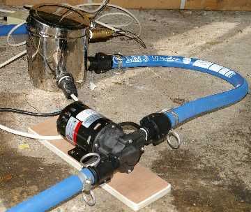
and eventually with the nice hose and the March 809 pump when it turned up from March May:
Image

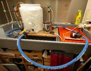
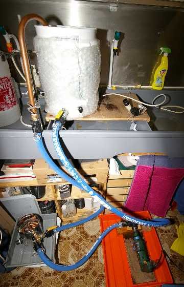
Finally I got to brew with it last weekend (20th of April), in the garage:
Image
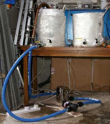
Here it is on the floor with the March pump - you can see the Camlock hose fittings:
Image

Using the HERMS system with the PID controller was a joy, once I'd sorted-out a few calibration problems. The temperature steps were a piece of p*** and to change up by 10 degrees took about 10 or 15 minutes. After the brew the bottling department asked where was the element covered in black crud, as seen previously when I heated the mash directly in the Electrim boiler, and I had to explain that this was the point - the element in the boiler had pre-heated the mash liquor and then done the main boil, so it only had a bit of light brown fur from the boil, which came off easily with a toothbrush!

If anyone wants a bit of pre-coiled 15mm pipe I have these leftover bits:
Image

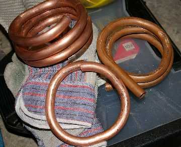
so send me a PM and I'll put one in the post for you.
Last edited by edit1now on Sat Apr 26, 2008 6:23 pm, edited 1 time in total.

User avatar
brewsters millionths
Hollow Legs
Posts: 412
Joined: Thu Aug 30, 2007 2:57 pm
Location: alton

Post by brewsters millionths » Sat Apr 26, 2008 7:06 pm

excellent post with plenty of photos for illustration.
congratulations.

User avatar
mixbrewery
Drunk as a Skunk
Posts: 831
Joined: Mon May 21, 2007 7:48 pm
Location: Hemel
Contact:

Post by mixbrewery » Sat Apr 26, 2008 7:12 pm

Nice work M.
Will you be doing a "show & tell" at the next LAB meeting. :lol:
Check out the beers we have for sale @ Mix Brewery

Vossy1

Post by Vossy1 » Sat Apr 26, 2008 7:18 pm

There's nothing we homebrewers can't overcome :lol:
Nice work e1n 8)

User avatar
edit1now
Under the Table
Posts: 1408
Joined: Wed Nov 28, 2007 5:09 pm
Location: North-west London

Post by edit1now » Sat Apr 26, 2008 9:08 pm

Mix - probably just point them at this thread!

Thanks for the kind remarks, guys.

jaytee1

Post by jaytee1 » Sun Apr 27, 2008 2:42 pm

ingenious use of a storage tin :D

buzzrtbi

Post by buzzrtbi » Mon Apr 28, 2008 1:41 pm

looks good mate - good fettling.

BUT - what is the difference between HERMS and RIMS?

User avatar
Aleman
It's definitely Lock In Time
Posts: 6132
Joined: Sun Jun 03, 2007 11:56 am
Location: Mashing In Blackpool, Lancashire, UK

Post by Aleman » Mon Apr 28, 2008 2:00 pm

buzzrtbi wrote:what is the difference between HERMS and RIMS?
HERMS - HEAT EXCHANGE Recirculation Mash System
RIMS- Recirculating Infusion Mash System

They both do the same thing, A RIMS generally uses a small electrical heater in a heat chamber to heat the wort directly as it recirculates (Like Mine, Steve Flack and Andy's). HERMS Passes the wort though a copper coil in a water bath to raise / stabilse the mash temp.

buzzrtbi

Post by buzzrtbi » Mon Apr 28, 2008 3:30 pm

thanks Aleman.

so when you recirculate into the mashtun is this just piped straight back in at the top. following the mash rest and drain do you then sparge as normal?

User avatar
Aleman
It's definitely Lock In Time
Posts: 6132
Joined: Sun Jun 03, 2007 11:56 am
Location: Mashing In Blackpool, Lancashire, UK

Post by Aleman » Mon Apr 28, 2008 3:55 pm

Well what I do (Others may differ) is to start draining the mash tun and then to start sparging before the tun is drained, keeping the sparge liquor just below the surface of the grain.

Of course there is nothing to stop you doing a batch sparge using a rims/herms, and I may very well try this on a couple of brews

buzzrtbi

Post by buzzrtbi » Mon Apr 28, 2008 5:00 pm

confused to what the heat exchange actually does then?

i thought the purpose was to get maximum efficency from the grain in stages such as

PROTEIN REST

SACCHARIFICATION REST
and

MASH-OUT REST

using different temperatures to break down the malt?

otherwise what else are you pumping about?

also you say keep the liquer BELOW the surface of the grain - is this correct?

User avatar
Aleman
It's definitely Lock In Time
Posts: 6132
Joined: Sun Jun 03, 2007 11:56 am
Location: Mashing In Blackpool, Lancashire, UK

Post by Aleman » Mon Apr 28, 2008 5:40 pm

You can use it to do multiple rests, but no malt needs that, in fact it can be detrimental to the beer if the mash spends too much time below 64C.

Consistency and repeatability is the main plus of RIMS/HERMS. If I mash at an indicated 66C I can be fairly confident that the mash is at 66C for as long as I want it, and can repeat it again one week/month/ year down the line.

Crystal clear wort is another plus ;)

When I am sparging then I prefer to keep the liquor just below the surface of the grain. In actuality it varies about 5mm above to 1cm below, although again there are times when I'm pretty lax about it and it can be a couple of inches above. Its not really a critical factor TBH as I am no longer into maximum efficiency brewing :D

buzzrtbi

Post by buzzrtbi » Mon Apr 28, 2008 8:32 pm

just being thick here then (apologies)

so where does the heat exchange come in then and the recirculation bit?

if youare mashing at the same temp (and a good insulated mash tun keeps the temp pretty constant) and you are sparging the same way I guess from a HLT. (mine is heavily insulated with 2 elements keeping the temperatre constant for sparging) where is the recirculation coming in to play? are you recirculating the runnings from the mash tun back into the top? if you are how are you doing this? (surely you cant be using the sparge arm - it would block up with chaff.)

just trying to understand how you guys are using the system. i can understand the aim to keep the temperature constant during mashing but from what you are saying above i cant see where the Recirculation is taking place?

apologies for being slow.. :roll:

Vossy1

Post by Vossy1 » Mon Apr 28, 2008 8:55 pm

are you recirculating the runnings from the mash tun back into the top?
Yes
(surely you cant be using the sparge arm - it would block up with chaff.)
Correct...certainly not a spinny type :wink:
if you are how are you doing this? (
See pics below for an example of a HERMS system. The mash tun outlet is connected to the pump

Image

The runnings are then pumped through a heat exchanger and back into the top of the mash

Image

User avatar
edit1now
Under the Table
Posts: 1408
Joined: Wed Nov 28, 2007 5:09 pm
Location: North-west London

Post by edit1now » Mon Apr 28, 2008 8:57 pm

Buzzrtbi - have a look at my Brewday post.

The first picture shows the mash tun on the left, with the mash liquor coming out of the ballvalve at the bottom and down to the March pump. The pump sends it into the bottom of the heat exchanger coil, which is heated by a kettle element in a couple of litres of water, then the liquor passes back up a hose and into the 22mm copper spout or U-tube, and back onto the top of the mash as seen in the second picture.

As I tried to explain in the Brewday post, I know I could do a straightforward 60 degree mash with just a well-insulated container and a supply of hot water, but...
a. I like making things and tinkering
b. Using the HERMS gives me absolute control over the temperatures so I can mess around with the malt, trying to get different characteristics like more body, less alcohol; or more maltiness and a less dry mouthfeel.
c. I'm hoping to scale-up this system to a larger-capacity one with shiny vessels, so I've invested in some reasonably good peripherals which I hope will just move across to the big one eventually. (OK that last bit wasn't relevant to your question: :oops: )

Does this help at all?

Post Reply